Hiển thị các bài đăng có nhãn Surface. Hiển thị tất cả bài đăng

Thứ Năm, 21 tháng 8, 2008

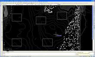
Using AECPolygon to Hide Surface Contours


I've been looking on the many hidden commands that are included in the program, but are undocumented. One of them is AECPolygon. One of the uses I thought of would be to hide surface contours with out having to select each polyline, like you would have to do with the boundary hide command. Learn more after the annoying jump...

You can use existing polylines or create the AECPOLYGON the same way you would draw a regular polyline. In this example I will create the AECPOLYGON's from existing polylines. To start type AECPOLYGON into the command line. Select the Convert option and select the PLines option. Select the polygons that you want converted to mask the surface.
If you want to keep the source polylines then select No, otherwise choose Yes. Now you will want to change the style of the newly created AECPOLYGON to do this press S for Style. A style manager will pop up onto the screen. Right click on AEC Polygon Styles and Choose New.Provide a name for the style, I choose HideContour. Go to the other tab and select Use Background Mask and select OK at the bottom of the screen.

Press enter to get out of the command. When you get out of the command you should notice that the style was not applied to the AECPOLYGON's.

To get them to show the correct style, select the AECPOLYGONs and go to properties and change it to show the style you created.
Now when you will have the surface contours will be hidden by the AECPOLYGON.


Unlike the Surface Boundary Hide, you have to worry about draworder and you can't print them from model space without changing the color of the mask (if you do it will come out as a black box). As long as you want the surface printed first it should be pretty easy to manage; send any surfaces to the back in which you don't want the contours being masked, then send the AECPOLYGONs to the back and then the Surface to be masked to the background.

This may also seem like the same as the wipeout command but there are somethings I like which are better, for instance you can add and remove vertexes throught the right click menu and there is an extra grip between vertexes that allows you to drag the edges and they stay parallel to the original line. Give it a try you may like it or not.

Disclaimer: I haven't actually used this in production, but will probably do so in the future.

viewmore

Thứ Tư, 20 tháng 8, 2008

Create a 3D Surface from a SHP File. (with survey extension)

Do you have the need to create a surface from a ESRI contour file, and that shape file is just 2D with the elevation as an attribute? The new released Survey Extension For Map3D will do it. It is as easy as 1, 2, 3.

Step 1. Use the data connect to connect to the shape file.

Connect_Shape

Note: all you need is to connect to it there is no need to add it to the map.

Step 2. Use the “Mapcreatesurface” command to open the Create Surface dialog.

Create_Icon

The Create surface tool is on the Input and Inquiry toolbar. if not just type the command at the command line.

Select_Connection

In the Create Surface Dialog, select “Connection” for the source and select the shp connection you made in the data connect.

Set_Z

Step 3. Provide a name and location for the Raster TIFF that will be created. Then select the field that contains the Elevation value in the attribute table.

Now press the OK button.

Now the results after setting a style to the surface feature layer and placing the original contours above it in the draw order.

Finished

OK if you count all the mouse clicks it may be more than 3 steps but, its quicker than firing up ArcInfo and using the tools to create the surface there then connect to it.

To those that may want to question the accurately of this compared to ESRI software, well I took the same shp file in ArcMAP created a TIN from it and converted that into a Raster. I then added that to this dwg and compared them in both 2D and 3D views. To me I didn’t see any difference between the two

viewmore

Surface From NED Files

Ok for all the Civil 3D and/or Land Desk Top users that have been asking on how to create a surface from the National Elevation Data (NED) files. Here is one way to create a C3D surface from of them. For those that are not aware the USGS site is now offering the format instead of the NED DEM from years ago.

First thing about this is when you download the files and unzip them is place the files in their own folder (directory) with a short path to them, do not unzip them to them same folder as other data or with a path a mile long, the shorter the better. Once you create the surface you can always go back and delete all the files anyways. I create a NED_Junk folder in my documents folder then clean house after I create my objects that I need. I used WinZip from the old DOS 5.1 days to unzip all the files into one folder, I notice using the windows zip app it unzips them into a two folders inside another folder.

In order to accomplish this task we need to use the Map 3D tools, so for you C3D users bring up the Map Task Pane, mapwspace at the command line. In the Display Manager, click on the Add Data icon to open up the data connect palette. In the Data Connect palette select the Raster Provider, use the file select icon and browse to the files you unzipped.

clip_image002

The Data Connect Palette.

When you get to the folder that contains the NED files, set the display to show the details. Look at the largest file there and that is the one we need.

clip_image004

The NED files.

The naming convention of them makes little to no sense so always find the largest one and use than. The rest of the files are used in “that other software” and MAP 3D can do with out them.

Once you selected the file Click the connect button on the Data Connect Palette. This will open another part of the palette and allow you to select the Schema to add to the map. In this case the schema is the file with the path.

clip_image006

The Data Connect Palette with the Schema listed.

Select the schema (check mark in the box) then click the Add to Map button.

Now you should have something display in the drawing area like below.

clip_image008

Don’t worry about how it looks or try to change the display of the features. All we need is for it to be part of the drawing (Map). You should also have some funny looking stuff in the Map’s Display Manager. For the non-map users this is called a map layer. The C3D toolspace is as confusing for Map users the same the Map Task Pane is to the C3D users. The thing we need to do is create an SDF file from the NED Raster. But it will be contours lines instead of a big blob. To do this in the Display Manager, right click on the NED layer and select Create Contour Layer.

clip_image010

In the Generate Contour Dialog, provide a name for the contour layer. Set the contour elevation intervals, (you can type in any value), then select the units you want them in. Browse to where you want to place the new SDF file and provide it a name. Finally click OK.

clip_image012

The Generate Contour Dialog.

The new SDF file and layer will be added to the map (drawing) and look like the below.

clip_image014

The NED Raster and the SDF Contours.

You display may be different depending on the NED file and what you set the contour interval to. At this point we don’t care what it looks like we got our data we need in fact close out the drawing, don’t even save it. What data we want is the Contour SDF file it created, I hope you remember the save location you selected in the generate contours dialog.

Open up a new blank drawing. What we need to is use the mapimport command to import the contour sdf file to create polylines and create object data attached to them. From the map menu select Tools>Import, set the file type to SDF and browse to your contour sdf file. If you do not know how to import and create the object data the image below is a quick lesson.

clip_image016

The Map Import of the SDF file and creating the Object Data.

Once you import the sdf file you will have polylines and object data attached to them, if you check the properties of one you notice it is at an elevation of “0” but the object data has the correct elevation listed. At this time save the drawing and close it out. We need to attach it to another new drawing and perform an alter-property query to alter the polylines elevation. So open a new drawing again and make sure the map task pane is open. Attach the saved drawing (the one you just saved and closed) using the map task pane. Now perform an alter-property query to set the polylines on their correct elevation. The image below is a refresher in accomplishing this if you need more “How-do” look here or here.

clip_image018

clip_image020

Once you do the alter-property query you now have contour line you can use to build a surface from. Make sure you de-attach the drawing you attached to before you start so if you crash from to many contour lines it will be save and not end up getting a map drawing lock on the file. Then of course go back and clean out all those NED files you unzipped and any other files you may have created, the only one you need to hold on to is the original zip file and maybe the contour sdf file you created, the rest are trash.

viewmore

"Deleting Multiple Surface Labels"

Every now and then we stumble across minor quirks in the program that will make it do undesirable things, like shut down. My post is not intended to discredit the program but to let people know about the issue and how to work around it. If for some odd reason you would like to replicate it follow the below steps.


1. Save your drawing!
2. Under Surface, Labels, Add Surface Labels
3. Add 4 or 5 labels to a surface, using Slope as the Label Type (only 2 are required)
4. Start the Erase command and select the 1st label, as you select the second label you will notice that the program will shut down unexpectedly.


This is just a minor flaw but I thought it was serious enough to share it with everyone out there. I guess the solution to it is to delete them one at a time. Also, I have noticed that it is only specific to the Slope Label Type. Just to be sure I have tried creating other label styles under the Slope Label Type and have had the same result.

I cannot take full credit for the finding but I can definitely replicate it. Autodesk has been notified and hopefully we will see a fix in the near future.

view more

Thứ Sáu, 15 tháng 8, 2008

Cut and fill

1. Make sure you have two surfaces created for comparison; i.e. an existing surface and proposed surface in C3D.
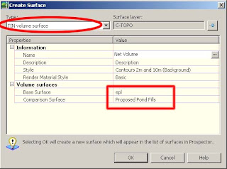
2. Next, create a new volume surface. There two methods for volume surface which are TIN volume or GRID volume. Choose either one and select your surfaces appropriately as shown in the diagram below:

3. Notice that when you hover your cursor (crosshair) over your Volume Surface, it will give you a +ve or –ve values depending on whether the area yield cut or fill as shown.
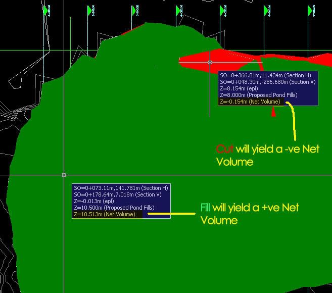
4. Once you have your Volume Surface created, you can begin to generate the Cut and Fill shade. In order to do that, you’ll need to go to the surface properties and choose the Elevation Banding (2D) (provided if you’ve created your drawing via the _Autodesk Civil 3D (Metric) NCS Classic template). Buzz me if you need illumination.

5. Subsequently, go to the Analysis tab. Choose only 2 ranges and click on run analysis. Change the Maximum Elevation values for ID no. 1 to 0 and the Minimum Elevation values for ID no. 2 to 0. 6. Click ok and you’re done. You might observe that at times your surface doesn’t mirror the surface you have in mind. Don’t fret, make use of the edit features under the surface properties i.e.; you can add Boundaries to show only the extent if your working area, cut/fill only…etc.
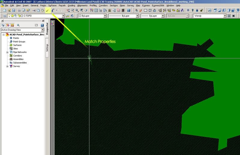
7. Last but not least, I have some engineers who came to me and ask whether C3D can generate the Cut and Fill shade in hatch pattern instead of hatch solid. Well the there is a workaround. The good thing with C3D is it comes together with AutoCAD and therefore it has the best of both worlds. What you need to do is to export the completed drawing to AutoCAD (File>Export>Export to AutoCAD)

8. Open your drawing using Civil3D as AutoCAD and you’ll notice that the solid hatch representing the cut and fill is not in 1 piece. This is the tedious part. You’ll need then to edit the hatch solid to another hatch pattern of your choice and inherit the properties using Match Properties. It’s not that hard after all…
Happy trying.


Tác giả : Wendy Lim Petaling Jaya, Selangor, Malaysia

Thứ Năm, 14 tháng 8, 2008

" How much surface is too much? "

There has been a lot of conversation in the Civil 3D community about large surface size.

One of the more common sources of large surface data files is aerial topography. Often, we are only provided with contours that have very close vertices. Sometimes we are able to get the DTM file or if we are really lucky the actual TIN or grid itself.

I have often had the experience of sitting down in an engineer's office and seeing what I would consider to be an unmanageablely large drawing. Upon inspection, aerial topography is the culprit.

I often recommend weeding the vertices of those contours before creating a surface from them and I am met with responses such as "we want to be as accurate as possible"

And I don't disagree with that. But I wanted to know exactly how much accuracy would be lost by doing a little bit of vertex elimination.

Here are some aerial topographic contours.

I built a surface from them "as is" called EG.

Then I weeded the contour vertices using the Map Cleanup>Simplify Objects command. I set the distance to 1ft.

Here are the results:

Drawing with nothing but EG surface in it: approx. 11 Meg
Drawing with nothing but EG1 surface in it: approx. 3 Meg


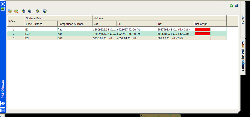
I made a flat surface at elevation zero to use as a comparison. I took a composite volume between EG and Flat, EG1 and Flat, and EG and EG1


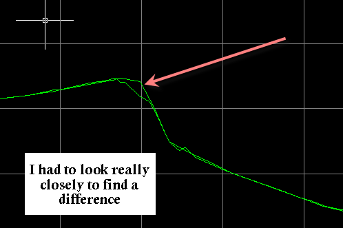
I also did a quick profile to see if there was a visible difference between the two surfaces. I did this a few places- here is just one of them. The results were similar- very few visible differences. And those that were visible were very small.


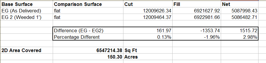
Here is a table of results comparing the two surfaces. (Note that you can click on it to see it larger).

Over the whole surface, 150 acres +/-, I discovered a difference of just about 3% in net volume.


Is this significant? You tell me. You are the PE on the job.

But think about this: if those differences are not significant, you are bogging down your drawing with an unnecessarily large surface.

Also- consider that you can reduce the simplification factor. I did 1Ft. In the past I have worked with clients who used 0.5ft and it made enough of a difference in drawing size to make it worth it.

You be the judge- I'd love to hear your comments!!! Please let me know if I missed something here.
Tác giả : Dana Breig Probert- an author of Mastering AutoCAD Civil 3D 2008.

"Civil 3D Nuts and Bolts: Volume Calculations and Making a Volume Exhibit"


Civil 3D 2006 and 2007 have a few ways you can do volume calculations. They include (but may not be limited to): Volumes from Corridor Sections, "Quick" Volumes, and building a Volume Surface.

Today we will talk about Quick Volumes and Volume Surfaces, including a way to make an exhibit that highlights your areas of Cut/Fill.

Remember, any image can be enlarged by clicking on it.

Start with your existing surface and proposed surface (or any two surfaces you need to compare). Your surface can be from grading objects, corridors, your own points, pasted surfaces, whatever it takes. Remember that if you built your corridor surface from the "TOP" codes, that your results won't just be earth volumes, but also stone and asphalt, etc. You can eliminate that problem by building another corridor surface from "DATUM" or "SUBGRADE"


For the Quick Volume go under the Civil 3D Surfaces Menu and Choose Utilities>Volumes


Make a volume entry, then choose the two surfaces that you would like to compare. BANG, done. If you change either surface (ie move a proposed ground profile so that your corridor updates) these numbers can be refreshed right away. This method is great for iterations.


Once you have come up with your optimized design, perhaps you want to make a volume surface. Picture your two surfaces as plates and fill in their differences with playdough. when you remove the plates, the playdough stays behind making a volume surface. Volume surface elevations and therefore contours, etc. are the difference between the two surfaces that made it. For example if you had a flat surface at elevation 10, and a flat surface at elevation 85, when you queried the elevations of the resulting volume surface, its elevation would be listed as 75.

To make a volume surface, Civil 3D Surfaces Menu>Create Surface. Choose TIN or Grid, then the style, and which surfaces you want to compare/contrast.

Now CRUNCH this volume surface and apply an elevation banding style of your preference so that you can show this to your client- where her trouble areas are for cut and fill.


Tác giả : Dana Breig Probert-an author of Mastering AutoCAD Civil 3D 2008.

Thứ Tư, 6 tháng 8, 2008

Copying a Surface

ROAD Wire Frame

I still get asked a lot how to copy a surface with Civil 3D. This is a really important step to become familiar with prior to pasting surfaces together. So here's how:

  1. To copy a surface (DTM) in Civil 3D, select the surface and then right-click.
  2. In the pop-up menu select BASIC MODIFY TOOLS, then select COPY.
  3. When prompted to enter the base point, enter 0, 0 at the command line, and press ENTER.
  4. When prompted to enter the second point, press ENTER
  5. Notice the new surface in Prospector.
  6. Right-click on the new surface and select SURFACE PROPERTIES.
  7. Type in a new appropriate name for the new surface.

Surface breaklines

Apologies for disappearing for the last couple of weeks from here.

I see Ove has been throwing some great things up here anyway, you must try the contour tool and dont forget the automatic rebuild on your surface!!

Anyway, this week I am at the home of CIvil 3D in Manchester, NH meeting with all the developers etc.

Back home today, but I thought I would post you something to look at

When adding a breakline to a surface, you may have seen that around your radius corners you dont have much detail in the surface and also along large spaces in any straight lines you get very big triangles.

Standard.jpg


What we need is to add some extra detail to the surface without adding more points to the feature lines

panel.jpg

This panel shows a 'mid-ordinate distance' - this is used to tessellate the polyline arcs from which the breakline is being created.

Selecting ‘Supplementing distance’, is used to add more triangles along straights in the breakline to create a smoother surface.

The result would be this

With factors.jpg

This can really improve your surfaces but without adding more points to your linework, which in turn can save you a lot of time in setting levels and gradients.

Surface from Breaklines


Q: Why does it seem like Civil 3D is ignoring parts of my breaklines?


A: Ahhh. When you added these to your surface as breaklines you had a Middle Ordinate Distance (MOD) that was too high.


Q: HUH?

A. Middle Ordinate Distance is the perpendicular distance between an arc and the midpoint of a chord. See the fun little picture to the left. M is mid-ordinate distance. M= R-R*cos (delta angle/2)


Q. Huh?


A. Never mind. All you need to know is that the smaller the Middle ordinate distance you set when adding breaklines to your surface, the finer Civil 3D chops up your curves when triangulating.


Q. Can't it triangulate to an arc directly?


A. Nope. A triangle leg must be straight.


Q. So, where is this "setting" you speak of?
A. As you add the breaklines, you get this dialog box. Give your breaklines a sensible name in case you need to modify them from prospector at a later date.

The smaller the Mid-ordinate distance, the tighter the triangles along the arcs in your breakline.
Q. So whats supplementing distance?
A. You can even add verticies on straight lines. So say you are adding a big straight line and want nice triangulation along it. Set that supplementing distance to, like, 50.' Normally it isn't a big deal.
But hey, you are getting off topic. Do you want me to talk about your breaklines or not?
You're going to want to remove the breaklines from your surface definition before you re-add them with the new M.O.D. setting. Right click on the name in prospector and select delete.
Right-click on breaklines in the Surface Definition in Prospector and select Add. You'll get the dialog we're looking for.

Surface analysis

What I'll post on this week is a fairly simple tips but I know some users have not gotten used to changeing the Styles. That's why I have to write some rows about it. ;-)

If you want to change the analysis style of a Surface you can do like this.
Below is a normal Surface with a contour style.
11-1.png

Hit Properties and select a Style presenting, for example, Color Analysis.
11-2.png

Go to the tab "Analysis" in the same dialog box.
11-3.png

This is where you set the "type" of analys you want to present.
Choose a number for "Ranges" and hit the "arrow".
11-4.png

Double click the color bars under "Scheme: " and select preferred colors. The same for selecting "Range Details" / Elevations. See below.
11-5.png

This will give you a simple map with colored elevations.
11-6.png