I start out by drawing a polyline across my surface. This represents the centerline alignment of my water line.
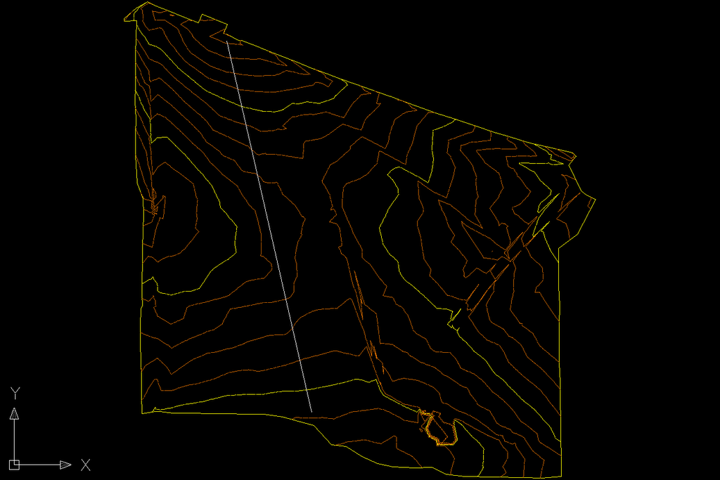
Turn the polyline into a feature line.
I like to keep my drawings organized so I choose to create an "H20-1" site to place the feature line in. Style is not important and erasing the existing entities will not affect the end result.

Project the feature line to the Surface.

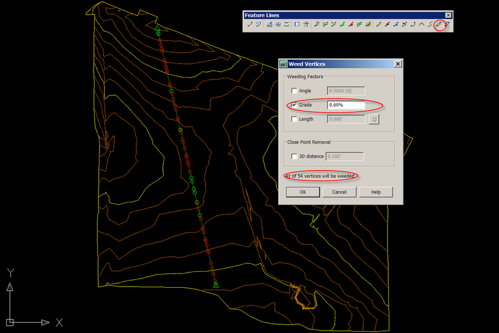
Notice now that we have quite a few vertices in our feature line, in fact, too many! We need to "weed" out some of those vertices to prevent our pipe network from being a bunch of little pipe segments. To accomplish this, we will use the "Weed vertices" button on our feature line tool bar. I choose to set the criteria to %0.60, you may find that a different percentage or a combination of angle and distance yields a better result for your situation.
Select the Feature line, right click, and go to the elevation editor. This is where you will use the Lower Incrementally button to set the depth of your water line. In my case, 4' below natural ground.*
*The feature line will define the center of the pipe. So, since I lowered my feature line 4' and I am building a 12" water line, I will have 3 1/2' of cover.

The next step is to create a parts list from which our network will be created. On the pipes tab add waterever pipe material and size of pipe that suits your design need. If you can't find the material you like, look here. On the structures tab DO NOT add any structures. Simply modify the style and the rules being used.

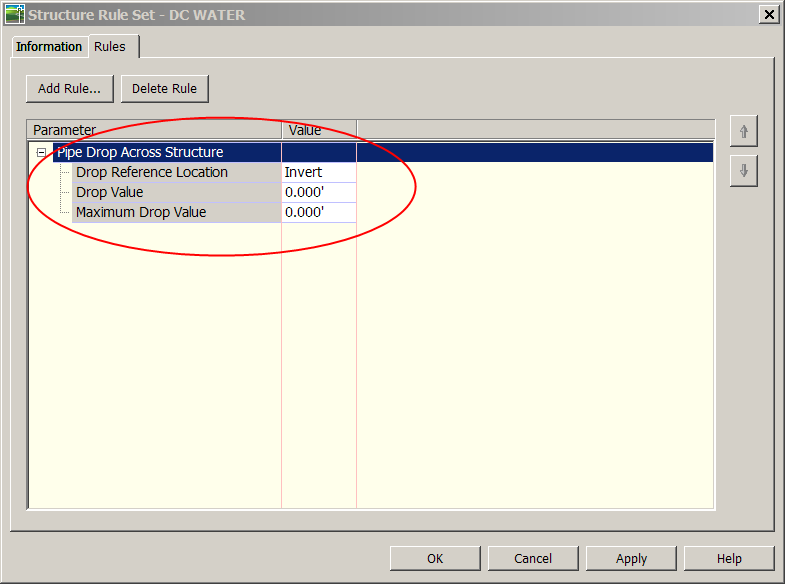
The rules being applied to the pipes and structures are key in this process. Here is how they should be set up.
Pipes:
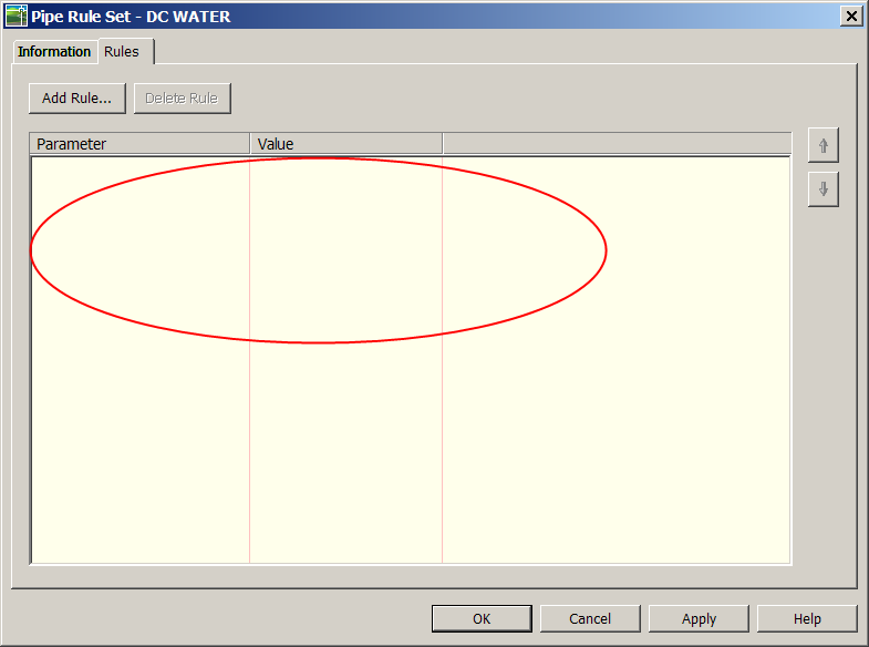
No, there is no mistake here. I've actual created a rule set that has no rules.
Structures:
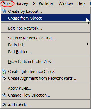
Before we turn our feature line into a pipe network we need to edit our "CreateNetworkFromObject" command setting.

There are three setting that need to be adjusted:
Default parts List, Pipe Default Rules, Structure Default Rules

With the settings set...we can now turn our feature line into a pipenetwork
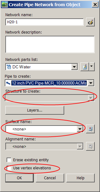
After selecting the feature line the below dialog box will show up. Notice that the option to choose a structure has been grayed out. Also be sure NOT to select a surface and make sure "Use vertex elevations" is NOT checked.
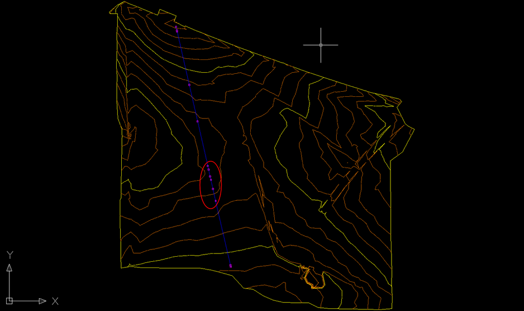
At first glance, it appears that we have now placed structures at all the remaining vertices....
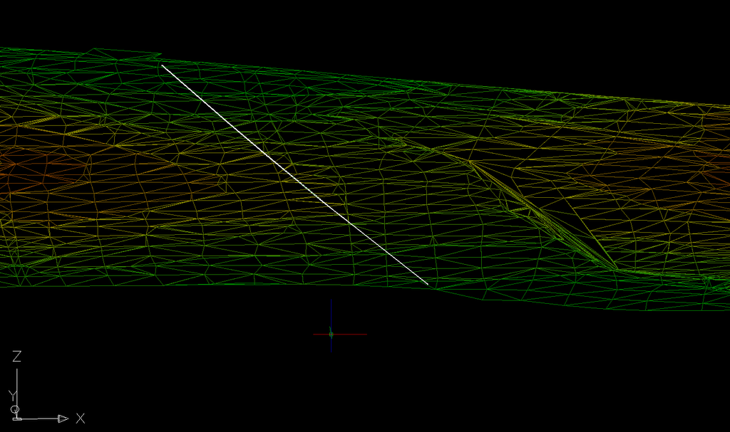
But, as we roll the model up into 3-D, we see that indeed, no structures were placed in our network
At this point we have completed laying out our network, but we still need to get it into a profile. And what's the first step of creating a profile? Well, we need an alignment, so let's create an alignment from network parts.
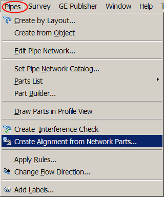
Choose the first "structure", then the last "structure", and then hit enter to confirm the selection.

Well organized sites and thought out names for objects and styles make it easy to breeze through dialog boxes like this. Make sure to check "Create profile and profile view"
Add the Natural ground surface, and then draw it in a profile view.

Adjust the profile view to your liking.

Place the profile view somewhere in your drawing and you should have something that looks like this!
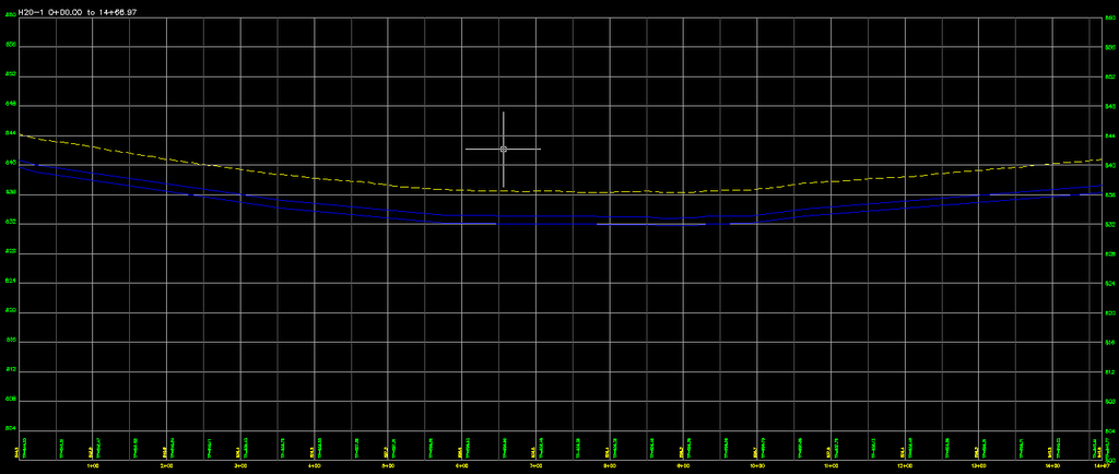
The final step is to clean up the plan view. Browse to the structures of the H20-1 network in the prospector. In the preview pane select all the structures, move your cursor to the heading of the styles column, right click and select edit. Select and more appropriate style, one that does not use a block in plan or profile view.

Looking back at the plan view you can see that everything looks as expected.

Look for some upcoming posts as we take this waterline profile a little closer towards a construction document.


