This tip is solely Peter's doing, and I can neither confirm nor deny any of the credit!
Displaying cut/fill labels with appropriate colors.

View image
Here is the end result of this tip. Note that the cut volume labels are red, and the fills are green, and they are each inserted on a grid.
Here is how to do it:
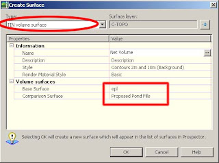
1. Create a volume surface that represents the two surfaces you are comparing
2. Create an expression for Surface Spot Elevation labels
- Name it "Negative Value"
- Use this expression; -1 * {Surface Elevation}

View image
This expression will take a value, and multiply it by negative one, changing a positive integer into a negative one, or for this case, taking a negative and turning it into a positive. The ole double negative trick!
3. Create a new Surface label style for Spot Elevation Called "Cut Fill"
- Rename the label Component to "fill"
- Change its color to Green
- Modify the Surface Elevation label component
- Edit the text component and change the Sign Modifier to "Hide Negative Value"

View image
4. Make a new component for the Cut value
- Copy the Fill text component
- Rename to Cut
- Change the color to Red
- Edit the Text Component, and replace with the Negative Value expression
- Change the Sign Modifier to "Hide Negative Value"

View image
Now add Surface labels to the Volume surface on a grid, using the Cut Fill style. All the spot elevation in a cut area (the negative values from the volume surface) will be labeled with the Red label, and all the spot elevations with a fill area (where the volume surface is positive) will label with the green text. Because we chose to hide the negative values, and we used an expression to turn a negative into a positive (the cut), it automatically display the appropriate spot elevation.

View image
view more


 3. Notice that when you hover your cursor (crosshair) over your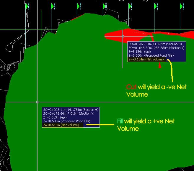
 6. Click ok and you’re done. You might observe that at times your surface doesn’t mirror the surface you have in mind. Don’t fret, make use of the edit features under the surface properties i.e.; you can add Boundaries to show only the extent if your working area, cut/fill only…etc.