Thứ Bảy, 9 tháng 8, 2008

2.1-Creating a New Triangulation Surface

Các bước thực hiện:

Theo đường dẫn sau để tìm đến file cad cho bài thực hành này :\Help\Civil 3D Tutorials ->Surface-1A.dwg.

1-To create a Triangulation surface ( tạo một mặt lưới đo đạc tam giác )

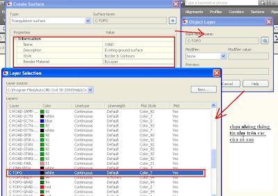
Click Surfaces menu -> Create Surface.

Trong mục surface properties, chọn như sau


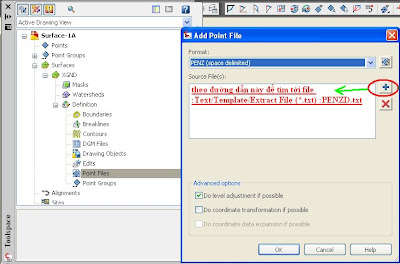
2-To add point data to a surface ( nhập vào dữ liêu điểm cho bề mặt )
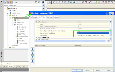
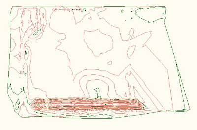
Thực hiện như hướng dẫn sau, sau đó click chuột phải chọn zoom to trong XGND surface được tạo để thấy kết quả hiện thị trên màn hình.


Ta có thể hiểu chỉnh dạng bề mạng bằng cách vào lại hộp thoại surface properties để chỉnh chon các lựa chọn các kiểu bề mặt trong mục surface style.
3-To add breaklines to a surface ( thêm đường breakline vào bề mặt đã tạo )
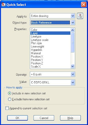
  1. Trong dòng lệnh ( command line) , enter QSelect.
  2. Trong hộp thoại Quick Select, dùng những lựa chọn sau :
    • Apply To: Entire Drawing
    • Object Type: 3D Polyline
    • Properties: Layer
    • Operator: = Equals
    • Value: C-TOPO-BRKL
    • Include In New Selection Set: Selected

Sau đó trong dòng lệnh, gõ lệnh Qselect, sau đó chọn những thông tin như hộp thoại sau:


Trong XGND surface, trong mục Definition. Click chuột phải Breaklines. Click Add.

Hộp thoại Add Breaklines, sau đó chọn những thông tin sau:

  • Description: XGND-Breaklines
  • Type: Standard
  • Mid-Ordinate Distance: 1.0000
4-Adding an Outer Boundary to a Surface ( thêm vào đường giới hạn cho bề mặt vừa tạo )
Tương tự như bước 3 ta cũng insert đường bao ngoài ( boundary ) vào bề mặt dc tạo.
Chọn thông tin như sau ở hộp thoại add boundaries
  • Name: XGND-Outer
  • Type: Outer
  • Non-Destructive Breakline: Cleared
  • Mid-Ordinate Distance: 1.0000


Bài thực hành đến đây đã kết thúc, hẹn gặp lại ở bài thực hành sau :Working with Large Surfaces
Exercise 1: Creating a New Triangulation Surface

Thứ Sáu, 8 tháng 8, 2008

1.3-Creating User-Defined Properties

Các bước thực hiện
1-To create user-defined classifications and properties ( tạo ra một sử dụng cá nhân và xác định những sự phân loại và những đặc tính trong nó ).
File để thực hiện bài học được lấy theo đường dẫn sau : \Help\Civil 3D Tutorials, mở bản vẽ Points-4.dwg .
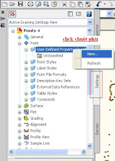
Từ thanh Toolspace, trong Settings tab, di chuyển đến Point collection. click chuột phải User-Defined Property Classifications. Click New
trong hộp thoại User-Defined Property Classification, enter Manhole UDP sau đó click ok.

làm lại bước trên sau đó chọn ở hộp thoại Manhole UDP properties những giá trị sau :
Name Property Field Type
MH_Material String
MH_Diameter Dimension
MH_Pipe In Diameter Dimension
MH_Pipe In Material String
MH_Pipe Out Invert Level
MH_Pipe Out Diameter Dimension
MH_Pipe Out Material
MH_Pipe In Invert
String
Level
Tạo một additional user-defined property classification được đặt tên là Trees
Thực hiện lại bước tương tự trên với các giá tri trong Trees classification
  1. Name Property Field Type
    Tree_Common Name String
    Tree_Genus String
    Tree_Species String
    Tree_Diameter Dimension
    Tree_Height Distance
2-To add a label style that displays user-defined property information ( tạo kiểu nhãn hiển thị cho thông tin cá nhân đã được xác định )


Bài học đến đây đã kết thúc, buổi kế tiếp sẽ tiếp tục thực hành bài : create surface
Thân chào !


1.2-Displaying and Editing Points

Các bước thực hiện.
Có thể lấy kết quả của bài học creating point data hoặc có thể lấy 1 file có sẵn trong mục cài đặt civil 3D theo đường dẫn sau :\Help\Civil 3D Tutorials chọn Points-2.dwg.
1- Externally referenced drawing ( hiệu chỉnh bên ngoài bản vẽ ).
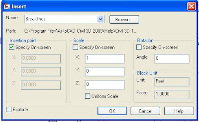
Trên thanh công cụ chọn Insert menu -> DWG Reference sau đó theo đường dẫn\Help\Civil 3D Tutorials tìm đến file Existing Basemap.dwg sẽ xuất hiện bảng sau ( chọn những thông tin như trên bảng ) :

2-To change the style of a point group ( thay các kiểu cho nhóm điểm )


3-To change the point group display order (thay đổi sự hiển thị của nhóm điểm ):


4-Removing an Externally Referenced Drawing (xóa một hiệu chỉnh bên ngoài bản vẽ ):

click chuột phải Existing Basemap.dwg sau đó chọn như tab trên

5-Editing Points ( chỉnh sửa điểm ) :
Tìm theo đường dẫn trên chọn Points-3.dwg để thực hiện bước này.
Thực hiện theo chỉ dẫn sau :


Thay đổi point style phía dưới thẻ display được hiển thị ở hộp trên ( có nhiều kiểu point style để lựa chọn, mỗi point style đềucó một hình dạng khác nhau. sau khi thay đổi màn hình sẽ biểu thị kiểu điểm đã được thay đổi.
Bài học đã kết thúc, hẹn gặp lại ở bài học sau : Adding User-Defined Properties to Points

Thứ Năm, 7 tháng 8, 2008

1.1-Creating point data

Các bước thực hiện
1-Từ file cài đặt mở dữ liệu điểm theo đường dẫn sau:\Help\Civil 3D Tutorials/-> open file :Points-1.dwg .
2- Thực hiện theo hướng dẫn sau

Hãy đặt tên cho key set và mô tả chúng theo như hộp thoại sau đó click OK.

3-Quay trở lại thanh toolspace, click chuột phải vào Stormwater keys mà bạn đã tạo để xuất hiện hộp thoại sau :

Chúng ta tiến hành thay đổi những thông tin sau đây: Code -><POND*> , Layer: chọn V-NODE-STRM, Point Style and Point Label Style có thể điều chỉnh trong mục settings bằng cách sử dụng point group properties. Tạo một code mới và làm thực hiện các bước tương tự, ta được bảng sau, Sau cùng click vào biểu tượng khoanh tròn góc phải.

4- Tạo một point groups.

Làm tương tự : Name: Storm Manholes. Raw Desc Matching: MHST*
5- Trong Toolspace, thẻ Prospector tab, di chuyển đến Point Groups collection. Right-click vào All Points collection. Click Properties

6- Nhập điểm từ database

Trong Toolspace, thẻ Prospector tab, click chuột phải vào _All Points của point group. Click Zoom To, ta được kết quả như sau :


Bài học đầu tiên đã kết thúc, hẹn gặp lại ở bài học tiếp theo "Displaying and Editing Points "
Chúc vui ! :D

Water Lines, Gas Lines, Electrical Conduit

Water Lines, Gas Lines, Electrical Conduit and everything else that doesn't have to flow down hill can be a bit tricky to show using pipes in C3D. That doesn't mean it's not possible though. Follow along to see how.

I start out by drawing a polyline across my surface. This represents the centerline alignment of my water line.
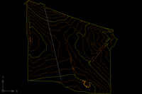

Turn the polyline into a feature line.

I like to keep my drawings organized so I choose to create an "H20-1" site to place the feature line in. Style is not important and erasing the existing entities will not affect the end result.
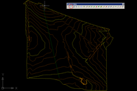

Project the feature line to the Surface.
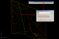

Notice now that we have quite a few vertices in our feature line, in fact, too many! We need to "weed" out some of those vertices to prevent our pipe network from being a bunch of little pipe segments. To accomplish this, we will use the "Weed vertices" button on our feature line tool bar. I choose to set the criteria to %0.60, you may find that a different percentage or a combination of angle and distance yields a better result for your situation.
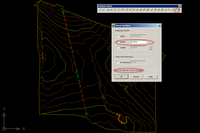

Select the Feature line, right click, and go to the elevation editor. This is where you will use the Lower Incrementally button to set the depth of your water line. In my case, 4' below natural ground.*

*The feature line will define the center of the pipe. So, since I lowered my feature line 4' and I am building a 12" water line, I will have 3 1/2' of cover.


The next step is to create a parts list from which our network will be created. On the pipes tab add waterever pipe material and size of pipe that suits your design need. If you can't find the material you like, look here. On the structures tab DO NOT add any structures. Simply modify the style and the rules being used.
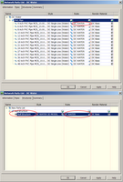

The rules being applied to the pipes and structures are key in this process. Here is how they should be set up.

Pipes:
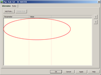
No, there is no mistake here. I've actual created a rule set that has no rules.

Structures:
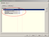

Before we turn our feature line into a pipe network we need to edit our "CreateNetworkFromObject" command setting.
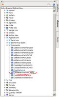

There are three setting that need to be adjusted:
Default parts List, Pipe Default Rules, Structure Default Rules


With the settings set...we can now turn our feature line into a pipenetwork
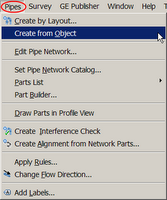

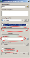
After selecting the feature line the below dialog box will show up. Notice that the option to choose a structure has been grayed out. Also be sure NOT to select a surface and make sure "Use vertex elevations" is NOT checked.

At first glance, it appears that we have now placed structures at all the remaining vertices....
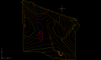

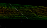
But, as we roll the model up into 3-D, we see that indeed, no structures were placed in our network

At this point we have completed laying out our network, but we still need to get it into a profile. And what's the first step of creating a profile? Well, we need an alignment, so let's create an alignment from network parts.
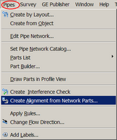

Choose the first "structure", then the last "structure", and then hit enter to confirm the selection.
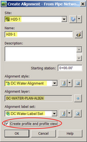
Well organized sites and thought out names for objects and styles make it easy to breeze through dialog boxes like this. Make sure to check "Create profile and profile view"

Add the Natural ground surface, and then draw it in a profile view.
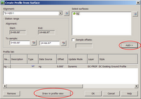

Adjust the profile view to your liking.
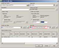

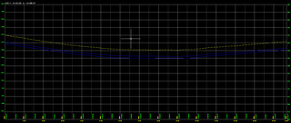
Place the profile view somewhere in your drawing and you should have something that looks like this!


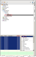
The final step is to clean up the plan view. Browse to the structures of the H20-1 network in the prospector. In the preview pane select all the structures, move your cursor to the heading of the styles column, right click and select edit. Select and more appropriate style, one that does not use a block in plan or profile view.

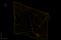
Looking back at the plan view you can see that everything looks as expected.

Look for some upcoming posts as we take this waterline profile a little closer towards a construction document.