3DDWFPREC - Controls the precision of 3D DWF publishing.
CAMERADISPLAY - Toggle camera objects display in the current drawing.
CAMERAHEIGHT - Stores the default height for newly created camera objects.
CLEANSCREENSTATE - Stores a value that indicates whether the clean screen state is on (read-only).
CMATERIAL - Sets the material of new objects.
CSHADOW - Sets the shadow display property for a 3D object.
DASHBOARDSTATE - Determines whether the Dashboard window is active or not.
DEFAULTLIGHTING - Turns default lighting on and off.
DEFAULTLIGHTINGTYPE - Specifies the type of default lighting.
DIMARCSYM - Controls display of the arc symbol in an arc length dimension.
DIMFXL - Sets the total length of the extension lines starting from the dimension line toward the dimension origin.
DIMFXLON - Controls whether extension lines are set to a fixed length.
DIMJOGANG - Determines the angle of the transverse segment of the dimension line in a jogged radius dimension.
DIMLTEX1 - Sets the linetype of the first extension line.
DIMLTEX2 - Sets the linetype of the second extension line.
DIMLTYPE - Sets the linetype of the dimension line.
DIMTFILL - Controls the background of dimension text.
DIMTFILLCLR - Sets the color for the text background in dimensions.
DRAGVS - Sets the visual style while creating 3D objects.
DWFFRAME - Determines whether the DWF frame is visible and if it will plot.
DWFOSNAP - Determines whether object snapping is enabled for DWFs that are attached to a DWG.
ERSTATE - "Determines whether the External References window is inactive - active/visible or active/auto-hidden."
GRIDDISPLAY - Controls the display behavior and display limits of the grid.
GRIDMAJOR - Controls the frequency of major grid lines compared to minor grid lines.
GRIDUNIT - Specifies the grid spacing (X and Y) for the current viewport.
GTAUTO - Controls whether or not grip tools display automatically when selecting objects in 3D space.
GTDEFAULT - "Controls whether or not the 3DMOVE, 3DROTATE, and 3DSCALE commands start automatically when the MOVE, ROTATE, and SCALE commands (respectively) are started in a 3D view."
GTLOCATION - Sets the default location for grip tools.
IMPLIEDFACE - Controls the detection of implied faces.
INTERFERECOLOR - Sets the color of interference objects.
INTERFEREOBJVS - Sets the visual style for interference objects.
INTERFEREVPVS - Sets the visual style for the current viewport while using the INTERFERENCE command.
LATITUDE - Specifies the latitude of the drawing model.
LEGACYCTRLPICK - Specifies the keys for selection cycling and the behavior for CTRL + left-click.
LIGHTGLYPHDISPLAY - Controls whether light glyphs are displayed.
LIGHTLISTSTATE - Indicates whether the Lights in Model window is open or closed.
LOFTANG1 - Sets the draft angle through the first cross section in a loft operation.
LOFTANG2 - Sets the draft angle through the last cross section in a loft operation.
LOFTMAG1 - Sets the magnitude of draft angle through the first cross section in a loft operation.
LOFTMAG2 - Sets the magnitude of draft angle through the last cross section in a loft operation.
LOFTNORMALS - Controls the normals of a lofted object where it passes through cross sections.
LOFTPARAM - Controls the shape of lofted solids and surfaces.
LONGITUDE - Specifies the longitude of the drawing model.
MATSTATE - Indicates whether the Materials window is open or closed.
NORTHDIRECTION - Specifies the angle of the Sun from north.
OSOPTIONS - Automatically suppresses object snaps on hatch objects and when you are using a dynamic UCS.
PERSPECTIVE - Specifies whether the current viewport displays a perspective working view.
PSOLHEIGHT - Sets the default height for a swept solid object created with the POLYSOLID command.
PSOLWIDTH - Sets the default width for a swept solid object created with the POLYSOLID command.
PUBLISHALLSHEETS - Controls how the Publish dialog list is populated.
RENDERPREFSSTATE - Stores a value that indicates whether the Advanced Render Settings palette is open.
SHADOWPLANELOCATION - Controls the location of an invisible ground plane used to display shadows.
SHOWHIST - Controls the Show History property for solids in a drawing.
SOLIDHIST - Controls the default History property setting for new and existing objects.
STEPSIZE - Specifies the step size in current units when users are in Walk mode.
STEPSPERSEC - Specifies the number of steps taken per second when users are in Walk mode.
SUNPROPERTIESSTATE - Indicates whether the Sun Properties window is open or closed.
SUNSTATUS - Controls whether the Sun is casting light in the viewport.
TIMEZONE - Sets the time zone for a sun study.
UCSDETECT - Controls whether dynamic UCS acquisition is active or not.
VSBACKGROUNDS - Controls whether backgrounds are displayed in the current viewport.
VSCURRENT - Stores the name of the visual style applied to the current viewport.
VSEDGECOLOR - Sets the color of edges.
VSEDGEJITTER - Controls the degree to which lines are made to appear as is they were sketched with a pencil.
VSEDGEOVERHANG - Makes lines extend beyond their intersection for a hand-drawn effect.
VSEDGES - Controls the types of edges that are displayed in the viewport.
VSEDGESMOOTH - Specifies the angle at which crease edges are displayed.
VSFACECOLORMODE - Controls how the color of faces is calculated.
VSFACESTYLE - Controls how faces are displayed in the current viewport.
VISUALSTYLES - "Displays the Visual Styles Manager palette - allowing you to create and modify visual styles or apply a visual style to a viewport."
VSHALOGAP - Sets the halo gap in the visual style applied to the current viewport.
VSHIDEPRECISION - Controls the accuracy of hides and shades in the visual style applied to the current viewport.
VSINTERSECTIONCOLOR - Specifies the color of intersection polylines in the visual style applied to the current viewport.
VSINTERSECTIONEDGES - Specifies the display of intersection edges in the visual style applied to the current viewport.
VSINTERSECTIONLTYPE - Controls whether obscured lines are displayed in the current viewport and sets their linetype.
VSLIGHTINGQUALITY - Sets the lighting quality in the current viewport.
VSMATERIALMODE - Controls the display of materials in the current viewport.
VSMONOCOLOR - Sets the color for monochrome display of faces.
VSOBSCUREDCOLOR - Specifies the color of obscured lines in the visual style applied to the current viewport.
VSOBSCUREDEDGES - Controls whether obscured (hidden) edges are displayed.
VSOBSCUREDLTYPE - Specifies the linetype of obscured lines in the visual style applied to the current viewport.
VSOPACITY - Controls the transparency of faces in the current viewport.
VSSHADOWS - Controls whether a visual style displays shadows.
VSSILHEDGES - Controls display of silhouette curves of solid objects in the visual style applied to the current viewport.
VSSILHEDGEWIDTH - Specifies the width in pixels for display of silhouette edges in the current viewport.
VSSPECULAR - Controls the display of specular highlights on faces without materials in the current viewport.
VSSTATE - Stores a value that indicates whether the Visual Styles window is open.
ZOOMWHEEL - Allows users to toggle the behavior of mouse wheel zoom operations.
Hiển thị các bài đăng có nhãn commands. Hiển thị tất cả bài đăng
Hiển thị các bài đăng có nhãn commands. Hiển thị tất cả bài đăng
Chủ Nhật, 24 tháng 8, 2008


Thứ Năm, 7 tháng 8, 2008
Adding LDT commands in C3D
If you have visited the discussions groups at all, you've heard that complaint/comment more than once. Well, there is simply no way to bring forward those commands. However, one can easily transfer over the toolbars and drop down menus from LDT into C3D. Once there, a quick modification of the macro inside of the CUI will have your menus and toolbars looking like LDT and working with the power of C3D. Follow along to see how.
As an example I've chosen the "Terrain: Edit Surface" toolbar. Why? Because almost every button on this toolbar has an equivalent command in C3D. Not every toolbar or pull down menu will work as nice, but if some of these basic commands can be brought over, it just might be that crutch that some of the more "hardened" end users need to make the transition.Start by firing up LDT and going to the CUI. Click on the transfer tab. On the right hand side open up the civil.cui located in ?:\Documents and Settings\USERNAME\Application Data\Autodesk\C3D 2007\enu\Support. Once the civil.cui file is open its a matter of drag and drop from one cui (land) to the other (civil).
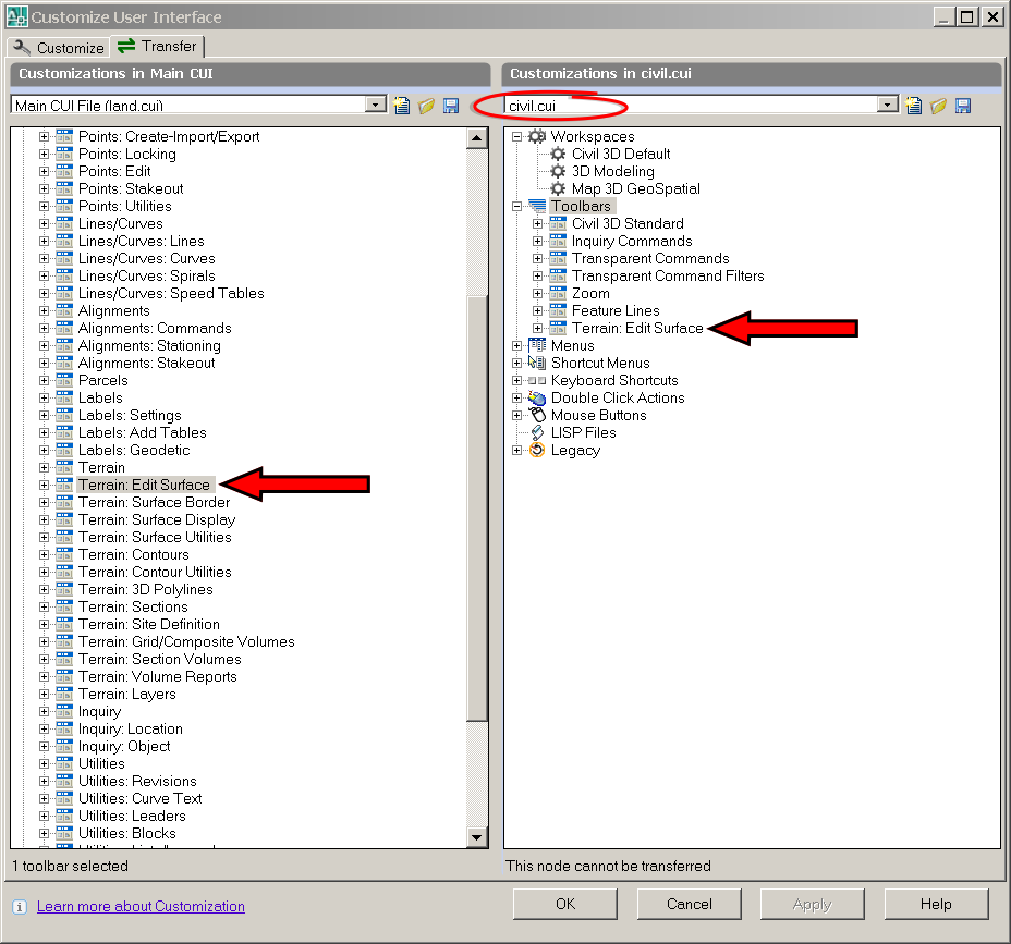
Now that we have the toolbar transferred from LDT to C3D, we can close down LDT and open up the CUI in C3D. Once in the CUI, browse in the toolbars until you find the "Terrain: Edit Surface" toolbar and expand it. By clicking on one of the commands under the toolbar you will populate the properties display pane. Here you will see the various fields we will need to edit.

The first button on the toolbar is "Import 3D lines". In LDT, it was necessary for one to import the 3d lines prior to editing the surface. In C3D it is only necessary for the current surface style to be displaying the triangles and/or points. I have chosen to populate this button with the EditSurfaceStyle command. This will allow the user to quickly access the surface style dialog box and turn on the triangles. EditSurfaceProperties would also be an acceptable command, so long as a surface style for editing has already been created. Wondering where I'm coming up will all these commands? Open up help and type in "Surfaces Command Reference", you will be given a result that contains a majority of the surface commands in C3D.
To edit the macro click on the contents of the macro in the display pane, then click on the ellipse.

Which will bring up the Long String Editor Dialog Box
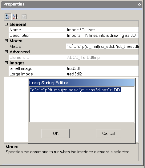
The macro should be composed as:

Notice how I've renamed the button and changed it's description.
The only thing we are missing now are the icon .BMPs. This is easier said than done, since all the .bmps are contained in a .dll instead of "free floating" .bmps like in years past. That's where Resource HackerTM comes into play. " Resource HackerTM is a freeware utility to view, modify, rename, add, delete and extract resources in 32bit Windows executables and resource files (*.res)." What that means to us, is the ability to extract all the nested bmps out of the .dll for use in our new toolbar and upcoming drop-down menu.
After downloading and extracting Resource HackerTM, start the program and open up the land.dll. You can find it here, ?:\Documents and Settings\USERNAME\Application Data\Autodesk\Autodesk Land Desktop 2007\R17.0\enu\Support. If your worried about messing up LDT, just make a copy for your use on the desktop. Once the file is open go to the Action drop down menu and Save All resources...

Choose a destination folder for all the soon-to-be extracted .bmps and the ".rc" file. Upon browsing to the chosen folder, you will find ~ 1630 bitmaps. They will be named "bitmap_1.bmp, bitmap_2.bmp, bitmap_3.bmp, etc." Decoding all these bitmaps is what the .rc file is for. Open up the .rc file with notpad and you will see something like this...

If we go back to the CUI, we can see which icons we are looking for. In this case "tred3dl" for the small image, "tred3dl2" for the large image. A quick search inside the notepad document will help you locate the various images. "tred3dl" happens to be "Bitmap_570.bmp". Edit the "Bitmap_570.bmp" file and rename it"tred3dl.bmp". You will need to repeat this process for every icon on the toolbar...I never said it was going to be fun or easy ;-)
After renaming the bmp, you will need to remap the icon location thru the cui. To keep things well organized, put all the renamed .bmps in the Icons folder located ?:\Documents and Settings\USERNAME\Application Data\Autodesk\C3D 2007\enu\Support\Icons
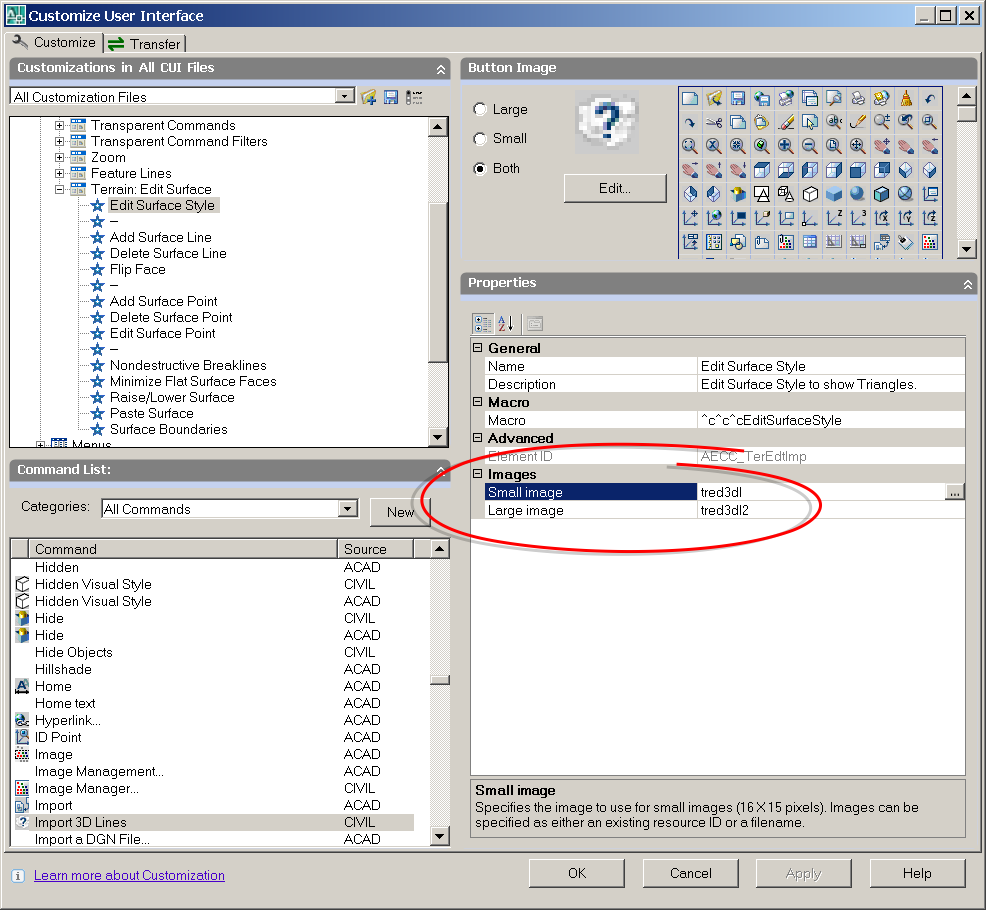
At this point, we have completed the process for the first button on the "Terrain: Edit Surface" toolbar. You will need to repeat this process for the remainder of the buttons.

Here is the list of macros I used to finish up the transfer:
Add Surface Line...........................^c^c^cAddSurfaceLine
Delete Surface Line......................^c^c^cDeleteSurfaceLine
Flip Face.........................................^c^c^cEditSurfaceSwapEdge
Add Surface Point.........................^c^c^cAddSurfacePoint
Delete Surface Point......................^c^c^cDeleteSurfacePoint
Edit Surface Point..........................^c^c^cEditSurfacePoint
Add Breaklines...............................^c^c^cAddSurfaceBreaklines
(^org. name of Nondestructive Breaklines)
Minimize Flat Surface Faces........^c^c^cMinimizeSurfaceFlatAreas
Raise/Lower Surface.....................^c^c^cRaiseLowerSurface
Paste Surface..................................^c^c^cEditSurfacePaste
Surface Boundaries.........................^c^c^cAddSurfaceBoundaries
Delete Surface Line......................^c^c^cDeleteSurfaceLine
Flip Face.........................................^c^c^cEditSurfaceSwapEdge
Add Surface Point.........................^c^c^cAddSurfacePoint
Delete Surface Point......................^c^c^cDeleteSurfacePoint
Edit Surface Point..........................^c^c^cEditSurfacePoint
Add Breaklines...............................^c^c^cAddSurfaceBreaklines
(^org. name of Nondestructive Breaklines)
Minimize Flat Surface Faces........^c^c^cMinimizeSurfaceFlatAreas
Raise/Lower Surface.....................^c^c^cRaiseLowerSurface
Paste Surface..................................^c^c^cEditSurfacePaste
Surface Boundaries.........................^c^c^cAddSurfaceBoundaries
And when everything is said and done...

Đăng ký:
Bài đăng (Atom)
