
 '>
'>
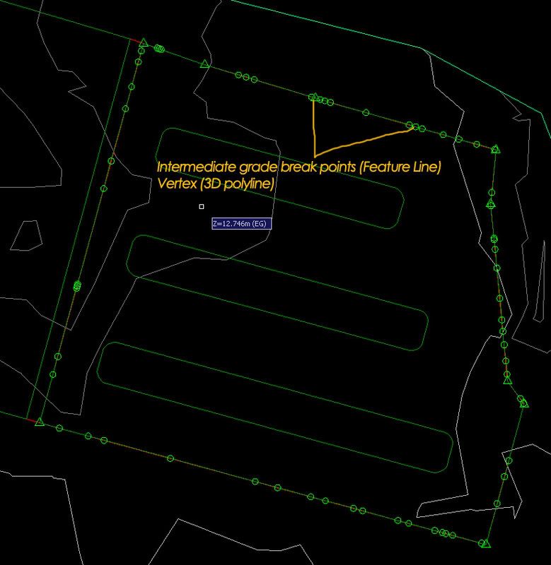
I got the result which is sufficient for me to generate my proposed surface but how about the slope scheme? I for one copy the feature line/3D polyline and paste it into a new drawing. Next, I simplify it by reducing the numbers of vertex but make sure you don't compromise on the accuracy. Then, try to the grading again. Remember, the main purpose of doing this is to get the slope schemes as you already have your projected line from the stepped offset function.
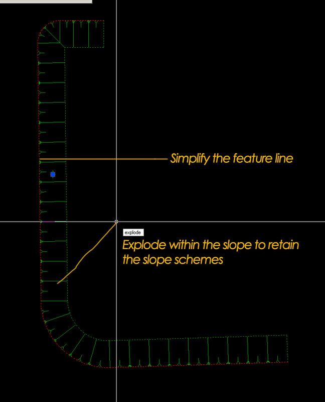
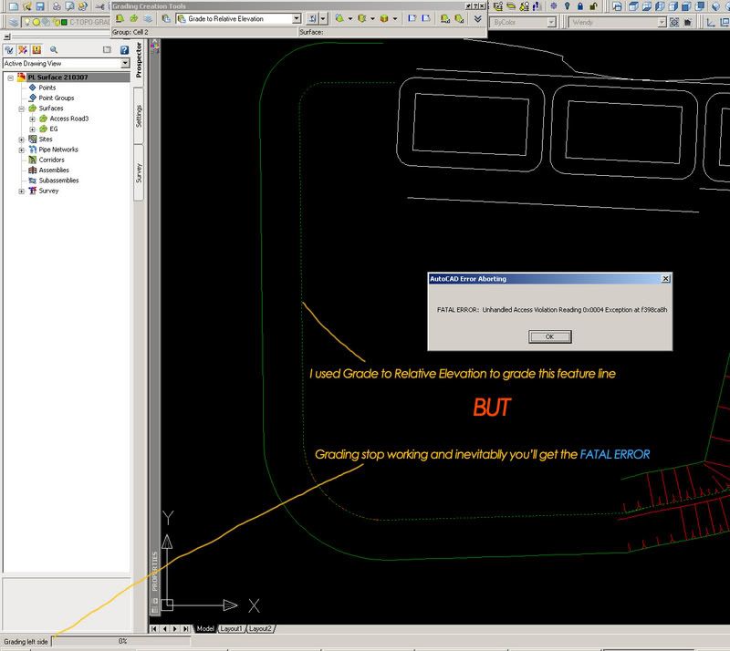
You then need to explode the slope because as alluded to earlier, the program crashed due to grading instability, thus you'll need to dissociate the grading component from the drawing. Note worthy of mention is that it is always a good practice to purge and perform audit check on the drawing to fix any errors within the drawing you are working on. I know this is a temporary measure and I've seen the sneak preview of C3D 2008 which has enhance the grading features considerably. Do click on the link to watch the webcast : https://www.livemeeting.com/cc/autodesklearning/view?id=Civil_RO-49&pw=Audience&cn
Meanwhile, I hope this post will benefit those whom are still using the older version. Cheers! "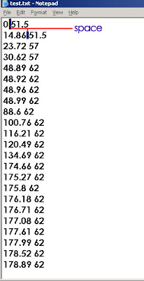 The first column is the station/chainage while the second column is the elevation of of the particular station/chainage. Just make sure that you stick to this format, otherwise you will not be able to import it. It really does come handy especially if I need to duplicate the profile...You can also create it from an elevation editor. Right click on the editor and click on copy all.
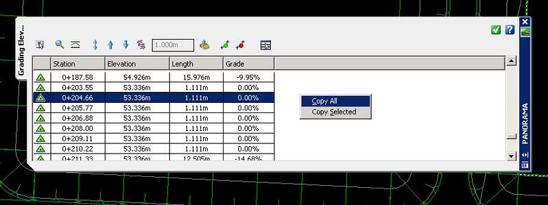
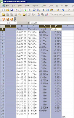
Make sure you replace the '+' and 'm' sign from the remaining columns. Select the area with numbers and copy it to a notepad: Then, with a bit of editing as follow:
 Save the txt file and you can start to create you profile from file.. "
Tác giả : Wendy Lim Petaling Jaya, Selangor, Malaysia
 3. Notice that when you hover your cursor (crosshair) over your Volume Surface, it will give you a +ve or –ve values depending on whether the area yield cut or fill as shown.
 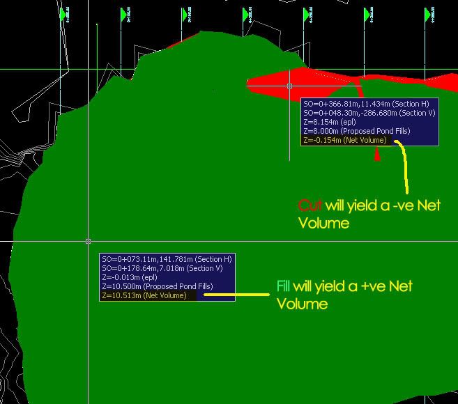 4. Once you have your Volume Surface created, you can begin to generate the Cut and Fill shade. In order to do that, you’ll need to go to the surface properties and choose the Elevation Banding (2D) (provided if you’ve created your drawing via the _Autodesk Civil 3D (Metric) NCS Classic template). Buzz me if you need illumination.
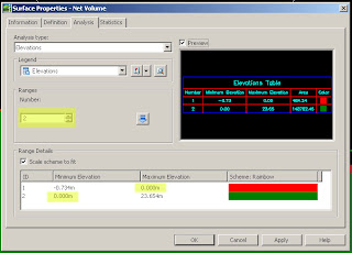 6. Click ok and you’re done. You might observe that at times your surface doesn’t mirror the surface you have in mind. Don’t fret, make use of the edit features under the surface properties i.e.; you can add Boundaries to show only the extent if your working area, cut/fill only…etc.
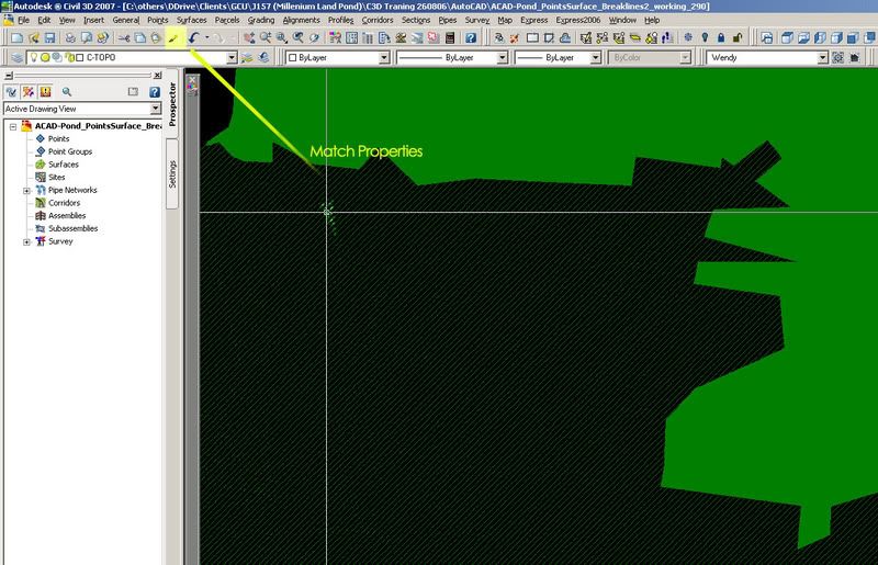 Happy trying.
 In the Customize User Interface dialog box, under the Workspace collection, select the workspace that you will like to customize. Notice that the contents of the workspace are displayed in the Workspace Contents pane to the right.
  In the Workspace Contents pane, click Customize Workspace to enter workspace editing mode. In the left pane, expand the Partial CUI Files collection, from this list you can select and include or exclude menus and toolbars from the different collection as it’s shown on the image. When you finish click Done to exit editing mode.
  Another cool thing about customize your workspace is that you can search for a particular command on the Command List pane under Search command list.
  Select it, drag and drop it in the toolbar that you want, so in this way you can have all the individual commands that you will like to work with, even if they are not originally in a particular toolbar…
  Click Apply to save the changes and them OK.


Civil 3D 2006 and 2007 have a few ways you can do volume calculations. They include (but may not be limited to): Volumes from Corridor Sections, "Quick" Volumes, and building a Volume Surface.
Today we will talk about Quick Volumes and Volume Surfaces, including a way to make an exhibit that highlights your areas of Cut/Fill.
Remember, any image can be enlarged by clicking on it.
Start with your existing surface and proposed surface (or any two surfaces you need to compare). Your surface can be from grading objects, corridors, your own points, pasted surfaces, whatever it takes. Remember that if you built your corridor surface from the "TOP" codes, that your results won't just be earth volumes, but also stone and asphalt, etc. You can eliminate that problem by building another corridor surface from "DATUM" or "SUBGRADE"
For the Quick Volume go under the Civil 3D Surfaces Menu and Choose Utilities>Volumes

Make a volume entry, then choose the two surfaces that you would like to compare. BANG, done. If you change either surface (ie move a proposed ground profile so that your corridor updates) these numbers can be refreshed right away. This method is great for iterations.

Once you have come up with your optimized design, perhaps you want to make a volume surface. Picture your two surfaces as plates and fill in their differences with playdough. when you remove the plates, the playdough stays behind making a volume surface. Volume surface elevations and therefore contours, etc. are the difference between the two surfaces that made it. For example if you had a flat surface at elevation 10, and a flat surface at elevation 85, when you queried the elevations of the resulting volume surface, its elevation would be listed as 75.
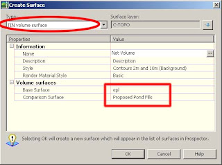
To make a volume surface, Civil 3D Surfaces Menu>Create Surface. Choose TIN or Grid, then the style, and which surfaces you want to compare/contrast.
Now CRUNCH this volume surface and apply an elevation banding style of your preference so that you can show this to your client- where her trouble areas are for cut and fill.


Tác giả : Dana Breig Probert-an author of Mastering AutoCAD Civil 3D 2008.


