Thứ Năm, 7 tháng 8, 2008

Profile-Incremental Stationing

That is what you'll notice too when you try and run the Profile-Incremental Stationing Report.

The VBA report is supposed to have the ability to list "PVI stations and elevations of the selected existing or finished ground profile at regular intervals, at critical geometry points, and crest and sag curve points." However, any profile created from a surface does not show up in the list of profiles in the drawing.


Proof that there are profiles in the drawing.


Come to find out the VBA routine only works on finished ground profiles, contrary to what the dialog box tells us. So we need to figure out how to get a FG profile to match our existing ground profile, with out tracing ;-)

It's actually pretty simple.
Step 1.) Create an assembly and add a marked point to it.


Step 2.) Create a corridor; use the alignment that the surface profile was created from as the baseline, use the surface profile as the profile, and use the simple assembly from step one. Your frequency really shouldn't matter so long as you have the option "At Profile Geometry Points" on.


Step 3.) Now that you have your corridor built...


Extract a profile from the corridor

C3D will prompt you to select a feature line; this should be easy since there is only one! After picking on the lone feature line, give the new profile an appropriate name and style.


After clicking OK, you can go to your profile view and verify that the new profile exactly matches the original.


Now, go back and run the report and you should see the extracted profile ready to have a report run on it.

Adding LDT commands in C3D

If you have visited the discussions groups at all, you've heard that complaint/comment more than once. Well, there is simply no way to bring forward those commands. However, one can easily transfer over the toolbars and drop down menus from LDT into C3D. Once there, a quick modification of the macro inside of the CUI will have your menus and toolbars looking like LDT and working with the power of C3D. Follow along to see how.

As an example I've chosen the "Terrain: Edit Surface" toolbar. Why? Because almost every button on this toolbar has an equivalent command in C3D. Not every toolbar or pull down menu will work as nice, but if some of these basic commands can be brought over, it just might be that crutch that some of the more "hardened" end users need to make the transition.

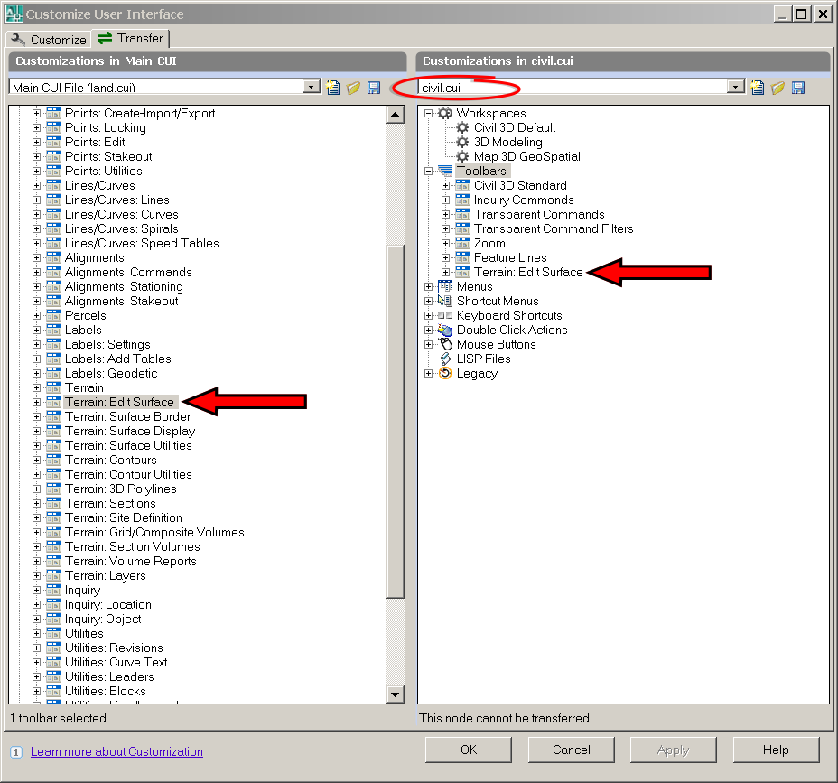
Start by firing up LDT and going to the CUI. Click on the transfer tab. On the right hand side open up the civil.cui located in ?:\Documents and Settings\USERNAME\Application Data\Autodesk\C3D 2007\enu\Support. Once the civil.cui file is open its a matter of drag and drop from one cui (land) to the other (civil).
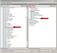


Now that we have the toolbar transferred from LDT to C3D, we can close down LDT and open up the CUI in C3D. Once in the CUI, browse in the toolbars until you find the "Terrain: Edit Surface" toolbar and expand it. By clicking on one of the commands under the toolbar you will populate the properties display pane. Here you will see the various fields we will need to edit.
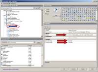

The first button on the toolbar is "Import 3D lines". In LDT, it was necessary for one to import the 3d lines prior to editing the surface. In C3D it is only necessary for the current surface style to be displaying the triangles and/or points. I have chosen to populate this button with the EditSurfaceStyle command. This will allow the user to quickly access the surface style dialog box and turn on the triangles. EditSurfaceProperties would also be an acceptable command, so long as a surface style for editing has already been created. Wondering where I'm coming up will all these commands? Open up help and type in "Surfaces Command Reference", you will be given a result that contains a majority of the surface commands in C3D.

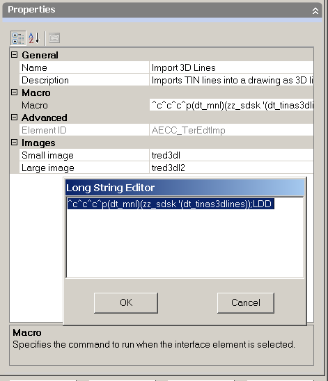
To edit the macro click on the contents of the macro in the display pane, then click on the ellipse.

Which will bring up the Long String Editor Dialog Box
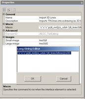

The macro should be composed as:
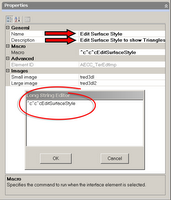
Notice how I've renamed the button and changed it's description.

The only thing we are missing now are the icon .BMPs. This is easier said than done, since all the .bmps are contained in a .dll instead of "free floating" .bmps like in years past. That's where Resource HackerTM comes into play. " Resource HackerTM is a freeware utility to view, modify, rename, add, delete and extract resources in 32bit Windows executables and resource files (*.res)." What that means to us, is the ability to extract all the nested bmps out of the .dll for use in our new toolbar and upcoming drop-down menu.

After downloading and extracting Resource HackerTM, start the program and open up the land.dll. You can find it here, ?:\Documents and Settings\USERNAME\Application Data\Autodesk\Autodesk Land Desktop 2007\R17.0\enu\Support. If your worried about messing up LDT, just make a copy for your use on the desktop. Once the file is open go to the Action drop down menu and Save All resources...
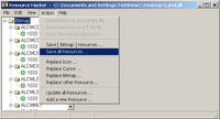

Choose a destination folder for all the soon-to-be extracted .bmps and the ".rc" file. Upon browsing to the chosen folder, you will find ~ 1630 bitmaps. They will be named "bitmap_1.bmp, bitmap_2.bmp, bitmap_3.bmp, etc." Decoding all these bitmaps is what the .rc file is for. Open up the .rc file with notpad and you will see something like this...
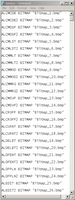

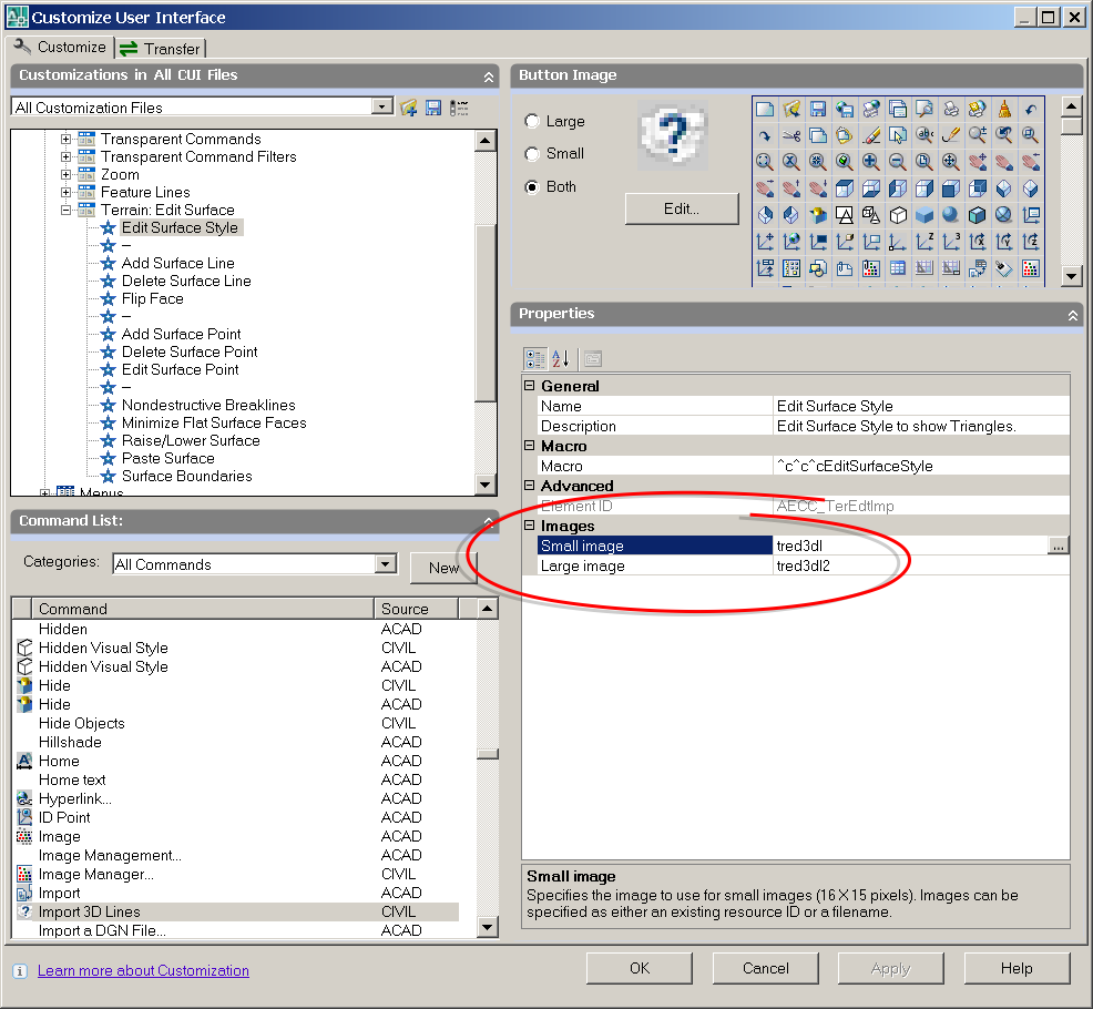
If we go back to the CUI, we can see which icons we are looking for. In this case "tred3dl" for the small image, "tred3dl2" for the large image. A quick search inside the notepad document will help you locate the various images. "tred3dl" happens to be "Bitmap_570.bmp". Edit the "Bitmap_570.bmp" file and rename it"tred3dl.bmp". You will need to repeat this process for every icon on the toolbar...I never said it was going to be fun or easy ;-)

After renaming the bmp, you will need to remap the icon location thru the cui. To keep things well organized, put all the renamed .bmps in the Icons folder located ?:\Documents and Settings\USERNAME\Application Data\Autodesk\C3D 2007\enu\Support\Icons
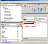

At this point, we have completed the process for the first button on the "Terrain: Edit Surface" toolbar. You will need to repeat this process for the remainder of the buttons.
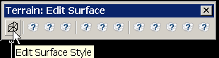
Here is the list of macros I used to finish up the transfer:

Add Surface Line...........................^c^c^cAddSurfaceLine

Delete Surface Line......................^c^c^cDeleteSurfaceLine

Flip Face.........................................^c^c^cEditSurfaceSwapEdge

Add Surface Point.........................^c^c^cAddSurfacePoint

Delete Surface Point......................^c^c^cDeleteSurfacePoint

Edit Surface Point..........................^c^c^cEditSurfacePoint

Add Breaklines...............................^c^c^cAddSurfaceBreaklines
(^org. name of Nondestructive Breaklines)

Minimize Flat Surface Faces........^c^c^cMinimizeSurfaceFlatAreas

Raise/Lower Surface.....................^c^c^cRaiseLowerSurface

Paste Surface..................................^c^c^cEditSurfacePaste

Surface Boundaries.........................^c^c^cAddSurfaceBoundaries

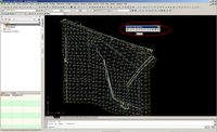
And when everything is said and done...


Critical Labels

Picking up were I left off yesterday, let's label all these critical points. Before I do though, I'd like to thank Angel for posting about my new blog. Thanks!

Labeling Critical Points
None of the out of the box labels really work the way I would like them to, but that doesn't mean that AutoDesk didn't provided the tools to make a label like I want!

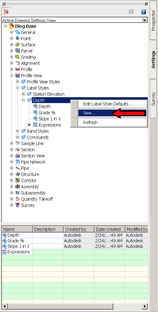
Let's start by making some new expressions. No, it's not a mistake, I am making the expressions under the Depth label category, even though I will eventually be labeling a station and elevation. Why? Because I like the look and feel of the depth label, it just doesn't label what I want it to...out of the box.


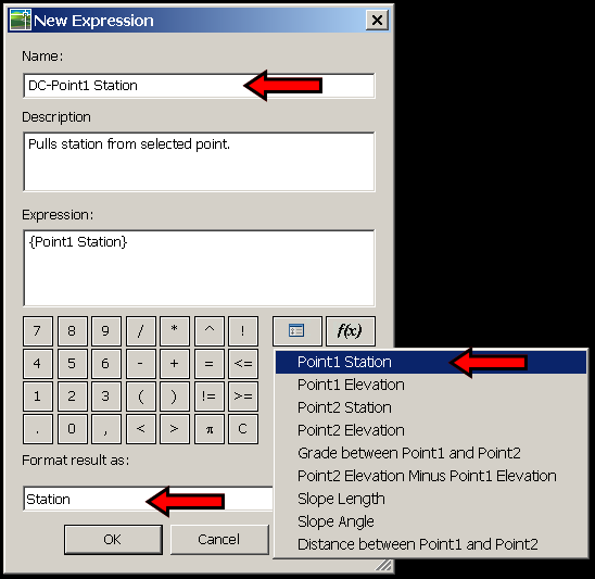
Two expressions need to be created. One for the station of the selected point and one for the elevation of said point. Pay close attention to the format that the results will displayed as. Now is a good time to extend your cad standards and naming convention to expressions.

Station Expression:


Elevation Expression:


Now that we have the expressions built, let's combine then into a label that we can use.

First, create a new label:


Now, let's format the label to take advantage of the new expressions:


After creating the new label style, it's time to label the critical points on our subject profile.
Profiles>Add Profile View Labels...

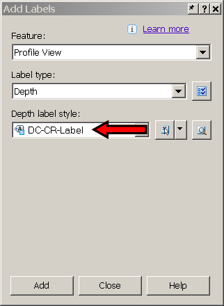
Now select the newly composed label:


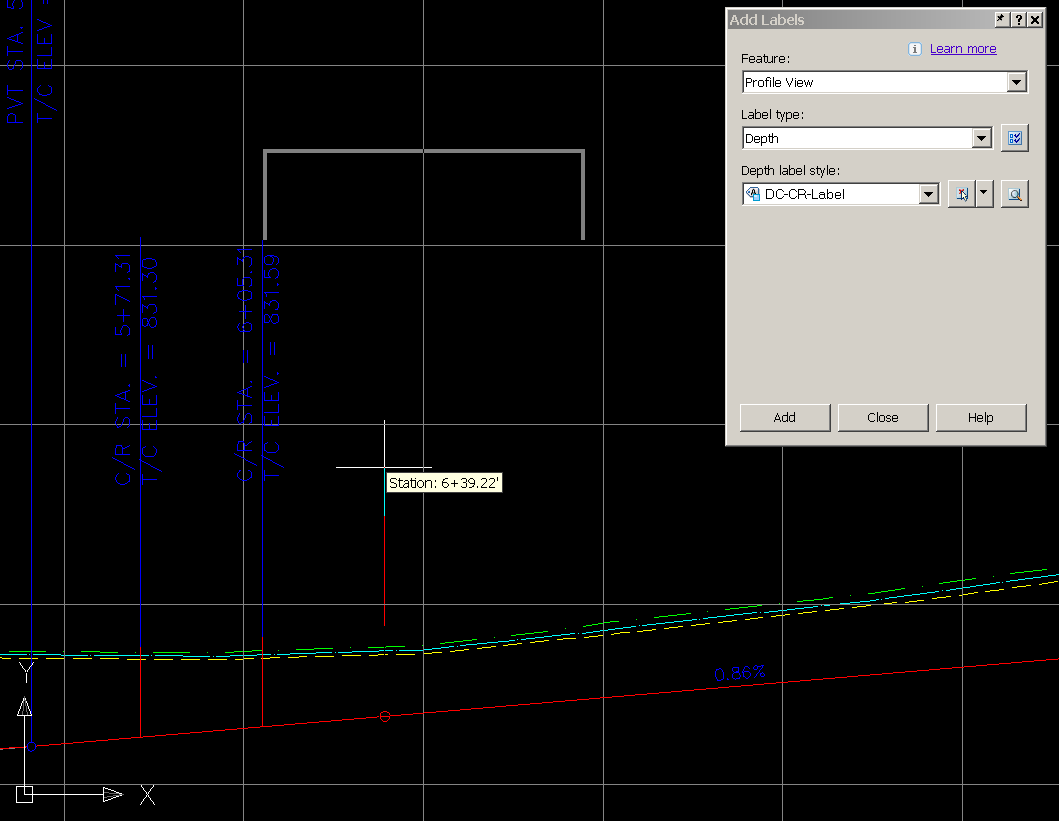
Adding the labels to the profile view is a breeze now that we have nodes to snap to (if you don't remember putting nodes on the profile, re-read yesterday's post). Simply snap onto the node of the various points and drag in the direction you want the label.


As a final cleanup, change the marker style of the "CR" point group to "none"


Now we have labeled all the curb returns, intersections, and any other critical stations without offseting or drawing any line in our profile view. Also, there was no need to label a single critical station in plan view for future reference!

Thứ Tư, 6 tháng 8, 2008

Using Layer Isolate in Civil 3D 2009

Here is a little tip that I'd like to pass your way...

Did you know that in 2008 the Layer ISOLATE command (originally the Express Layer Isolate command) was not only incorporated into AutoCAD®, but was also enhanced to give us a couple of options to control its behavior and what it did or did not display on screen? Well, it did and below are shown a couple of ways, in AutoCAD® Civil 3D® 2009, where you can adjust those settings to your choosing.

(Click to Enlarge)
Ribbon Panel Layer Isolate

Whether you select the command from Layers Ribbon Panel (like I have), the Layers II toolbar, the Format > Layer Tools, or typed LAYISO on the command line (yes, i too type many of my commands... but i needed a pretty picture), you can enter "S" for settings and then select O for Off or L for Lock and fade.

Layer Isolate

(Click to Enlarge)
Text Window

Another way is to select the Settings button Settings in the Layer Properties Manager, which can be found in the upper right corner of the manager and will display the Layer Settings dialog box where the Isolate Layer Settings that can be modified to your liking.

(Click to Enlarge)

Note: in the 2009, the Layer Properties Manager is modeless which means that it can remain open (floating or docked) and can be set to Auto-hide like other palettes found in AutoCAD.

My guess is that by now you are saying to yourself... Doug, why should I even care about what is set in the Layer Isolate settings. Well, you should care if you are trying to select "Drawing Objects" or "Contours", for example, as C3D surface data. If your Layer Isolate settings are set to "Lock and fade", then C3D won't add the data to the surface Definition. If you set the setting to "Off", then the data will be added to the surface and you will see the fruit of your labor.

Now don't get me wrong, I like the look and feel of the "Lock and fade"; however, that nice look and feel doesn't help me out when I am trying to add certain data types to my surface.

If you're already in the know about this because of another Blog or you've found it on your own, then back to work (just kidding, there is nothing wrong with nice mental break know and then). If this is new to you, then...

Corridor design - Part I

Corridor design used to be one of the scariest topics for many engineers, before Civil3D came along. I still remember my good old days with Geopak, when I used to spend days leading up to the anticipation of being able to see my highway in 2D view (cross-sections), let alone be able to view something in 3D. Along came CAiCE, however, and made the job much easier with the aid of Fragments, etc. But when Civil3D came along with its nifty assemblies and subassemblies, I felt like the job of design engineers' is just getting too easy now! It's funny I can back that up because I am currently at Univ. of Central Florida showing Civil 3D to faculty, students of Geomatics program including some survey professionals, and everyone seems to think engineers have it made.

So, corridors can be as simple or complex depending upon the scope of your project. If you do simple 2 or 4-lane rural or urban sections, it literally takes no time, whether in professional or educational setting. Interchanges, on the other hand, could get a bit involved, although same steps are needed to get to the end result. Complex interchanges (cloverleafs, etc.) have many ramps, alignments, etc. to keep track of, which is what really requires bulk of the work. The building blocks of corridor remain simple 1) alignment 2) Design Profile, 3) Assemblies, and 4) ground surface. Once you have these three pieces, it's a breeze creating a corridor model (which is the fancy 3D highway people love to see). 1

Check out this demo of corridor modeling >>>>

In next post, I will demonstrate the steps to create a simple assembly (think typical section or cross-section image of what the highway section would look like), and then get into putting a simple corridor together.